1 / 1
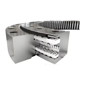
The external teeth mesh with the driving gear for transmission. The transmission ratio is accurate, the operation is smooth, and it can achieve controllable rotational movement. No external additional driving mechanism is required.
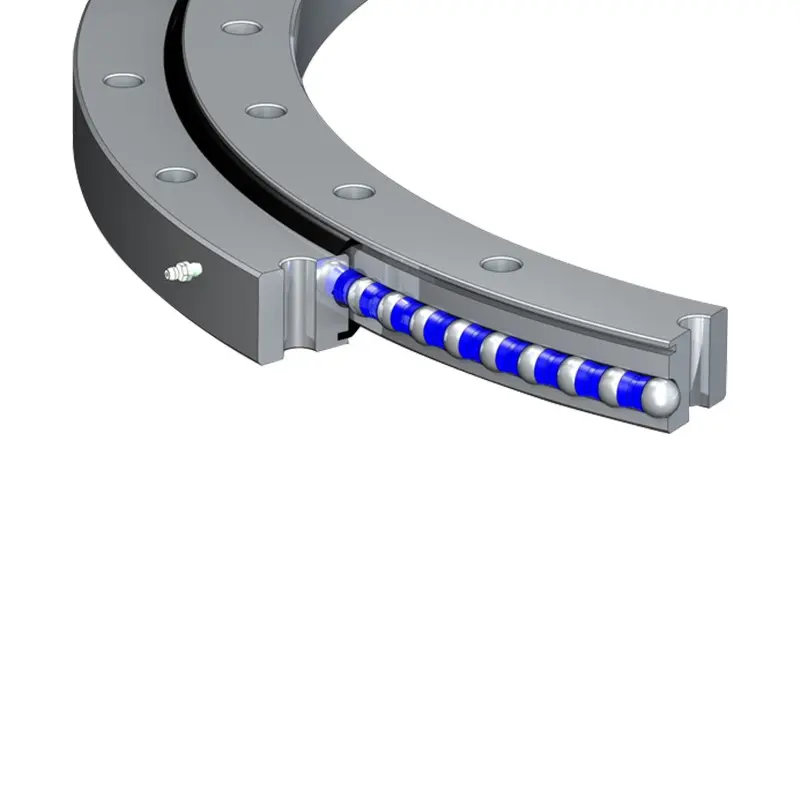
The rolling friction coefficient of the steel balls is low, the rotation is flexible, and it is suitable for material handling and rotary operations of construction machinery.
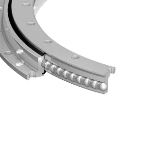
The sealing device can effectively prevent the leakage of lubricating oil and the intrusion of dust and impurities. Regular addition of lubricating oil can maintain good working conditions. The wear condition of the gear meshing surface needs to be checked regularly.
| 01 series of basic parameters | ||||||||||||||||||||
| Serial number NO. | Basic Size | Configuation Size | Mounting Size | Structural Size | Gear Data | Outer Gear Data | Inner Gear Data | |||||||||||||
| Outerine teeth | D | d | H | D1 | D2 | n | Bolt Hole | Screw Hole | n1 | H1 | h | b | x | m | da | Z | da | Z | ||
| Type o | Type 123 | |||||||||||||||||||
| D0 | Ø | Ø | T | |||||||||||||||||
| 1 | 011.20.200 | 280 | 120 | 60 | 248 | 152 | 12 | 16 | M14 | 28 | 2 | 50 | 10 | 40 | 0 | 3 | 300 | 98 | — | — |
| 2 | 011.20.224 | 304 | 144 | 60 | 272 | 176 | 12 | 16 | M14 | 28 | 2 | 50 | 10 | 40 | 0 | 3 | 321 | 105 | — | — |
| 3 | 011.20.250 | 330 | 170 | 60 | 298 | 202 | 18 | 16 | M14 | 28 | 2 | 50 | 10 | 40 | 0 | 4 | 352 | 86 | — | — |
| 4 | 011.20.280 | 360 | 200 | 60 | 328 | 232 | 18 | 16 | M14 | 28 | 2 | 50 | 10 | 40 | 0 | 4 | 384 | 94 | — | — |
| 5 | 011.25.315 | 408 | 222 | 70 | 372 | 258 | 20 | 18 | M16 | 32 | 2 | 60 | 10 | 50 | 0 | 5 | 435 | 85 | 190 | 40 |
| 6 | 011.25.355 | 448 | 262 | 70 | 412 | 298 | 20 | 18 | M16 | 32 | 2 | 60 | 10 | 50 | 0 | 5 | 475 | 93 | 235 | 49 |
| 7 | 011.25.400 | 493 | 307 | 70 | 457 | 343 | 24 | 18 | M16 | 32 | 2 | 60 | 10 | 50 | 0 | 6 | 528 | 86 | 276 | 48 |
| 8 | 011.25.450 | 543 | 357 | 70 | 507 | 393 | 24 | 18 | M16 | 32 | 2 | 60 | 10 | 50 | 0 | 6 | 576 | 94 | 324 | 56 |
| 9 | 011.30.500 | 602 | 398 | 80 | 556 | 434 | 20 | 18 | M16 | 32 | 4 | 70 | 10 | 60 | ±0.5 | 5 | 629 | 123 | 367 | 74 |
| 012.30.500 | 6 | 628.8 | 102 | 368.4 | 62 | |||||||||||||||
| 10 | 011.30.560 | 662 | 458 | 80 | 626 | 494 | 20 | 18 | M16 | 32 | 4 | 70 | 10 | 60 | ±0.5 | 5 | 689 | 135 | 427 | 86 |
| 012.30.560 | 6 | 688.8 | 112 | 428.4 | 72 | |||||||||||||||
| 11 | 011.30.630 | 732 | 528 | 80 | 696 | 564 | 24 | 18 | M16 | 32 | 4 | 70 | 10 | 60 | ±0.5 | 6 | 772.8 | 126 | 494.4 | 83 |
| 012.30.630 | 8 | 774.4 | 94 | 491.2 | 62 | |||||||||||||||
| 12 | 011.30.710 | 812 | 608 | 80 | 776 | 644 | 24 | 18 | M16 | 32 | 4 | 70 | 10 | 60 | ±0.5 | 6 | 850.8 | 139 | 572.4 | 96 |
| 012.30.710 | 8 | 854.4 | 104 | 571.2 | 72 | |||||||||||||||
| 13 | 011.40.800 | 922 | 678 | 100 | 878 | 722 | 30 | 22 | M20 | 40 | 6 | 90 | 10 | 80 | ±0.5 | 8 | 966.4 | 118 | 635.2 | 80 |
| 012.40.800 | 10 | 968 | 94 | 634 | 64 | |||||||||||||||
| 14 | 011.40.900 | 1022 | 778 | 100 | 978 | 822 | 30 | 22 | M20 | 40 | 6 | 90 | 10 | 80 | ±0.5 | 8 | 1062.4 | 130 | 739.2 | 93 |
| 012.40.900 | 10 | 1068 | 104 | 734 | 74 | |||||||||||||||
| 15 | 011.40.1000 | 1122 | 878 | 100 | 1078 | 922 | 36 | 22 | M20 | 40 | 6 | 90 | 10 | 80 | ±0.5 | 10 | 1188 | 116 | 824 | 83 |
| 012.40.1000 | 12 | 1185.6 | 96 | 820.8 | 69 | |||||||||||||||
| 16 | 011.40.1120 | 1242 | 998 | 100 | 1198 | 1042 | 36 | 22 | M20 | 40 | 6 | 90 | 10 | 80 | ±0.5 | 10 | 1298 | 127 | 944 | 95 |
| 012.40.1120 | 12 | 1305.6 | 106 | 940.8 | 79 | |||||||||||||||
| 17 | 011.45.1250 | 1390 | 1110 | 110 | 1337 | 1163 | 40 | 26 | M24 | 48 | 5 | 100 | 10 | 90 | ±0.5 | 12 | 1449.6 | 118 | 1048.8 | 88 |
| 012.45.1250 | 14 | 1453.2 | 101 | 1041.6 | 75 | |||||||||||||||
| 18 | 011.45.1400 | 1540 | 1260 | 110 | 1487 | 1313 | 40 | 26 | M24 | 48 | 5 | 100 | 10 | 90 | ±0.5 | 12 | 1605.6 | 131 | 1192.8 | 100 |
| 012.45.1400 | 14 | 1607.2 | 112 | 1195.6 | 86 | |||||||||||||||
| 19 | 011.45.1600 | 1740 | 1460 | 110 | 1687 | 1513 | 45 | 26 | M24 | 48 | 5 | 100 | 10 | 90 | ±0.5 | 14 | 1817.2 | 127 | 1391.6 | 100 |
| 012.45.1600 | 16 | 1820.8 | 111 | 1382.4 | 87 | |||||||||||||||
| 20 | 011.45.1800 | 1940 | 1660 | 110 | 1887 | 1713 | 45 | 26 | M24 | 48 | 5 | 100 | 10 | 90 | ±0.5 | 14 | 2013.2 | 141 | 1573.6 | 112 |
| 012.45.1800 | 16 | 2012.8 | 123 | 1574.4 | 99 | |||||||||||||||
| 21 | 011.60.2000 | 2178 | 1825 | 144 | 2110 | 1891 | 48 | 33 | M30 | 60 | 8 | 132 | 12 | 120 | ±0.5 | 16 | 2268.8 | 139 | 1734.4 | 109 |
| 012.60.2000 | 18 | 2264.4 | 123 | 1735.2 | 97 | |||||||||||||||
| 22 | 011.60.2240 | 2418 | 2065 | 144 | 2350 | 2131 | 48 | 33 | M30 | 60 | 8 | 132 | 12 | 120 | ±0.5 | 16 | 2492.8 | 153 | 1990.4 | 125 |
| 012.60.2240 | 18 | 2498.4 | 136 | 1987.2 | 111 | |||||||||||||||
| 23 | 011.60.2500 | 2678 | 2325 | 144 | 2610 | 2391 | 56 | 33 | M30 | 60 | 8 | 132 | 12 | 120 | ±0.5 | 18 | 2768.4 | 151 | 2339.2 | 125 |
| 012.60.2500 | 20 | 2776 | 136 | 2228 | 112 | |||||||||||||||
| 24 | 011.60.2800 | 2978 | 2625 | 144 | 2910 | 2691 | 56 | 33 | M30 | 60 | 8 | 132 | 12 | 120 | ±0.5 | 18 | 3074.4 | 168 | 2527.2 | 141 |
| 012.60.2800 | 20 | 3076 | 151 | 2528 | 127 | |||||||||||||||
| 25 | 011.75.3150 | 3376 | 2922 | 174 | 3686 | 3014 | 56 | 45 | M42 | 84 | 8 | 162 | 12 | 150 | ±0.5 | 20 | 3476 | 171 | 2828 | 142 |
| 012.75.3150 | 22 | 3471.6 | 155 | 2824.8 | 129 | |||||||||||||||
| 26 | 011.75.3550 | 3776 | 3322 | 174 | 3686 | 3414 | 56 | 45 | M42 | 84 | 8 | 162 | 12 | 150 | ±0.5 | 20 | 3876 | 191 | 3228 | 162 |
| 012.75.3550 | 22 | 3889.6 | 174 | 3220.8 | 147 | |||||||||||||||
| 27 | 011.75.4000 | 4226 | 3772 | 174 | 4136 | 3864 | 60 | 45 | M42 | 84 | 10 | 162 | 12 | 150 | ±0.5 | 22 | 4329.6 | 194 | 3660.8 | 167 |
| 012.75.4000 | 25 | 43451 | 171 | 3660 | 147 | |||||||||||||||
It is widely used in small and medium-sized cranes, excavators, loaders, rotary conveyors, concrete spreading machines, welding operation machines, small port machinery and environmental protection equipment, especially suitable for medium and light-duty equipment that requires active power rotation and has moderate load.
It is ideal for small to medium-sized cranes, excavators, loaders, rotary conveyors, concrete spreading machines, welding stations, environmental protection systems, and similar light-to-medium-duty rotary machinery.
The external gear design allows direct meshing with the drive gear. This delivers an accurate transmission ratio, guarantees smooth operation, and eliminates the need for complex external driving mechanisms.
Maintenance is straightforward. Ensure regular lubrication to prevent friction, check the integrity of the sealing device (which guards against dust and impurities), and periodically inspect the wear status of the gear teeth.
The low operating resistance is achieved through a optimized rolling configuration using steel balls. This minimizes the friction coefficient, resulting in highly flexible and efficient rotational movement.
These bearings are specifically designed for medium and light-duty equipment requiring moderate load capacity and active power rotation. For extreme heavy-duty needs, larger model series should be consulted.