1 / 1
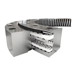
Small radial dimension: The gears are positioned inward, saving external space and minimizing the overall outer diameter of the slewing bearing.
The inner teeth are located inside and receive some degree of protection, making them less susceptible to direct impact from external contaminants.
Sometimes this is beneficial for the stability design of the entire equipment.
| 01 series of basic parameters | ||||||||||||||||||||
| Serial number NO. | Basic Size | Configuation Size | Mounting Size | Structural Size | Gear Data | Outer Gear Data | Inner Gear Data | |||||||||||||
| Inner teeth | D | d | H | D1 | D2 | n | Bolt Hole | Screw Hole | n1 | H1 | h | b | x | m | da | Z | da | Z | ||
| Type o | Type 123 | |||||||||||||||||||
| D0 | Ø | Ø | T | |||||||||||||||||
| 1 | — | 280 | 120 | 60 | 248 | 152 | 12 | 16 | M14 | 28 | 2 | 50 | 10 | 40 | 0 | 3 | 300 | 98 | — | — |
| 2 | — | 304 | 144 | 60 | 272 | 176 | 12 | 16 | M14 | 28 | 2 | 50 | 10 | 40 | 0 | 3 | 321 | 105 | — | — |
| 3 | — | 330 | 170 | 60 | 298 | 202 | 18 | 16 | M14 | 28 | 2 | 50 | 10 | 40 | 0 | 4 | 352 | 86 | — | — |
| 4 | — | 360 | 200 | 60 | 328 | 232 | 18 | 16 | M14 | 28 | 2 | 50 | 10 | 40 | 0 | 4 | 384 | 94 | — | — |
| 5 | 013.25.315 | 408 | 222 | 70 | 372 | 258 | 20 | 18 | M16 | 32 | 2 | 60 | 10 | 50 | 0 | 5 | 435 | 85 | 190 | 40 |
| 6 | 013.25.355 | 448 | 262 | 70 | 412 | 298 | 20 | 18 | M16 | 32 | 2 | 60 | 10 | 50 | 0 | 5 | 475 | 93 | 235 | 49 |
| 7 | 013.25.400 | 493 | 307 | 70 | 457 | 343 | 24 | 18 | M16 | 32 | 2 | 60 | 10 | 50 | 0 | 6 | 528 | 86 | 276 | 48 |
| 8 | 013.25.450 | 543 | 357 | 70 | 507 | 393 | 24 | 18 | M16 | 32 | 2 | 60 | 10 | 50 | 0 | 6 | 576 | 94 | 324 | 56 |
| 9 | 013.30.500 | 602 | 398 | 80 | 556 | 434 | 20 | 18 | M16 | 32 | 4 | 70 | 10 | 60 | ±0.5 | 5 | 629 | 123 | 367 | 74 |
| 014.30.500 | 6 | 628.8 | 102 | 368.4 | 62 | |||||||||||||||
| 10 | 013.30.560 | 662 | 458 | 80 | 626 | 494 | 20 | 18 | M16 | 32 | 4 | 70 | 10 | 60 | ±0.5 | 5 | 689 | 1355 | 427 | 86 |
| 014.30.560 | 6 | 688.8 | 112 | 428.4 | 72 | |||||||||||||||
| 11 | 013.30.630 | 732 | 528 | 80 | 696 | 564 | 24 | 18 | M16 | 32 | 4 | 70 | 10 | 60 | ±0.5 | 6 | 772.8 | 126 | 494.4 | 83 |
| 014.30.630 | 8 | 774.4 | 94 | 491.2 | 62 | |||||||||||||||
| 12 | 013.30.710 | 812 | 608 | 80 | 776 | 644 | 24 | 18 | M16 | 32 | 4 | 70 | 10 | 60 | ±0.5 | 6 | 850.8 | 139 | 572.4 | 96 |
| 014.30.710 | 8 | 854.4 | 104 | 571.2 | 72 | |||||||||||||||
| 13 | 013.40.800 | 922 | 678 | 100 | 878 | 722 | 30 | 22 | M20 | 40 | 6 | 90 | 10 | 80 | ±0.5 | 8 | 966.4 | 118 | 635.2 | 80 |
| 013.40.800 | 10 | 968 | 94 | 634 | 64 | |||||||||||||||
| 14 | 013.40.900 | 1022 | 778 | 100 | 978 | 822 | 30 | 22 | M20 | 40 | 6 | 90 | 10 | 80 | ±0.5 | 8 | 1062.4 | 130 | 739.2 | 93 |
| 014.40.900 | 10 | 1068 | 104 | 734 | 74 | |||||||||||||||
| 15 | 013.40.1000 | 1122 | 878 | 100 | 1078 | 922 | 36 | 22 | M20 | 40 | 6 | 90 | 10 | 80 | ±0.5 | 10 | 1188 | 116 | 824 | 83 |
| 014.40.1000 | 12 | 1185.6 | 96 | 820.8 | 69 | |||||||||||||||
| 16 | 013.40.1120 | 1242 | 998 | 100 | 1198 | 1042 | 36 | 22 | M20 | 40 | 6 | 90 | 10 | 80 | ±0.5 | 10 | 1298 | 127 | 944 | 95 |
| 014.40.1120 | 12 | 1305.6 | 106 | 940.8 | 79 | |||||||||||||||
| 17 | 013.45.1250 | 1390 | 1110 | 110 | 1337 | 1163 | 40 | 26 | M24 | 48 | 5 | 100 | 10 | 90 | ±0.5 | 12 | 1449.6 | 118 | 1048.8 | 88 |
| 014.45.1250 | 14 | 1453.2 | 101 | 1041.6 | 75 | |||||||||||||||
| 18 | 013.45.1400 | 1540 | 1260 | 110 | 1487 | 1313 | 40 | 26 | M24 | 48 | 5 | 100 | 10 | 90 | ±0.5 | 12 | 1605.6 | 131 | 1192.8 | 100 |
| 014.45.1400 | 14 | 1607.2 | 112 | 1195.6 | 86 | |||||||||||||||
| 19 | 013.45.1600 | 1740 | 1460 | 110 | 1687 | 1513 | 45 | 26 | M24 | 48 | 5 | 100 | 10 | 90 | ±0.5 | 14 | 1817.2 | 127 | 1391.6 | 100 |
| 014.45.1600 | 16 | 1820.8 | 111 | 1382.4 | 87 | |||||||||||||||
| 20 | 013.45.1800 | 1940 | 1660 | 110 | 1887 | 1713 | 45 | 26 | M24 | 48 | 5 | 100 | 10 | 90 | ±0.5 | 14 | 2013.2 | 141 | 1573.6 | 112 |
| 014.45.1800 | 16 | 2012.8 | 123 | 1574.4 | 99 | |||||||||||||||
| 21 | 013.60.2000 | 2178 | 1825 | 144 | 2110 | 1891 | 48 | 33 | M30 | 60 | 8 | 132 | 12 | 120 | ±0.5 | 16 | 2268.8 | 139 | 1734.4 | 109 |
| 014.60.2000 | 18 | 2264.4 | 123 | 1735.2 | 97 | |||||||||||||||
| 22 | 013.60.2240 | 2418 | 2065 | 144 | 2350 | 2131 | 48 | 33 | M30 | 60 | 8 | 132 | 12 | 120 | ±0.5 | 16 | 2492.8 | 153 | 1990.4 | 125 |
| 014.60.2040 | 18 | 2498.4 | 136 | 1987.2 | 111 | |||||||||||||||
| 23 | 013.60.2500 | 2678 | 2325 | 144 | 2610 | 2391 | 56 | 33 | M30 | 60 | 8 | 132 | 12 | 120 | ±0.5 | 18 | 2768.4 | 151 | 2339.2 | 125 |
| 014.60.2500 | 20 | 2776 | 136 | 2228 | 112 | |||||||||||||||
| 24 | 013.60.2800 | 2978 | 2625 | 144 | 2910 | 2691 | 56 | 33 | M30 | 60 | 8 | 132 | 12 | 120 | ±0.5 | 18 | 3074.4 | 168 | 2527.2 | 141 |
| 014.60.2800 | 20 | 3076 | 151 | 2528 | 127 | |||||||||||||||
| 25 | 013.75.3150 | 3376 | 2922 | 174 | 3686 | 3014 | 56 | 45 | M42 | 84 | 8 | 162 | 12 | 150 | ±0.5 | 20 | 3476 | 171 | 2828 | 142 |
| 014.75.3550 | 22 | 3471.6 | 155 | 2824.8 | 129 | |||||||||||||||
| 26 | 013.75.3550 | 3776 | 3322 | 174 | 3686 | 3414 | 56 | 45 | M42 | 84 | 8 | 162 | 12 | 150 | ±0.5 | 20 | 3876 | 191 | 3228 | 162 |
| 014.75.3550 | 22 | 3889.6 | 174 | 3220.8 | 147 | |||||||||||||||
| 27 | 013.75.4000 | 4226 | 3772 | 174 | 4136 | 3864 | 60 | 45 | M42 | 84 | 10 | 162 | 12 | 150 | ±0.5 | 22 | 4329.6 | 194 | 3660.8 | 167 |
| 014.75.4000 | 25 | 43451 | 171 | 3660 | 147 | |||||||||||||||
This design is ideal for equipment with strict installation space limitations, particularly when the maximum turning radius must be tightly controlled. Typical applications include port cranes, pile extractors, and wind turbine generators (yaw and tilt mechanisms), where compactness is essential for maneuverability and system integration.
The integrated gear-on-ring configuration eliminates the need for external gear sets by combining load-bearing and power transmission functions into a single component. This space-saving design also provides inherent protection for gear teeth against harsh environmental conditions such as salt spray, moisture, extreme temperatures, and debris contamination—ensuring long-term reliability with minimal maintenance.
By delivering both compactness and durability in demanding operating environments, this solution offers equipment manufacturers a reliable, low-maintenance alternative that extends service life while maintaining precise rotational control under complex loads.
The inward gear positioning significantly saves external space and minimizes the overall outer diameter of the slewing bearing, which is crucial for systems with strict radial space limits.
Since the inner teeth are positioned internally, they receive inherent protection from environmental hazards such as debris contamination, salt spray, moisture, and extreme temperatures.
They are highly recommended for compact heavy-duty systems including port cranes, pile extractors, and wind turbine generator yaw/tilt mechanisms.
Yes. The integrated gear-on-ring setup combines power transmission and load-bearing capacities into a single component, eliminating the need for independent external gear sets.
By shifting the gears inward, the center of gravity is positioned closer to the center, which supports better stability design and balancing for complex machinery.
The table provides comprehensive structural dimensions, mounting interfaces (including bolt and screw hole layouts), configuration sizes, and inner/outer gear data for the 01 series.